
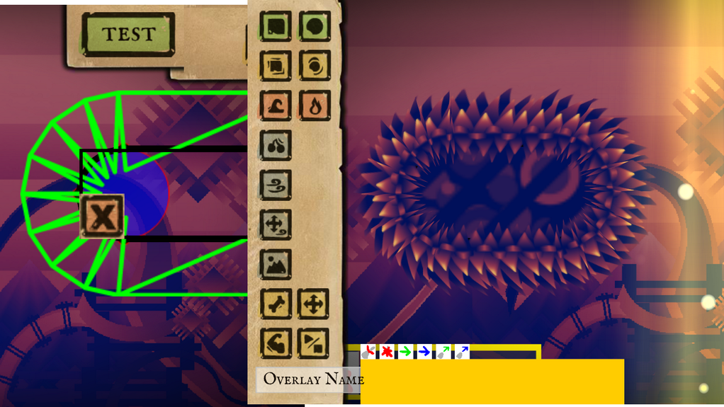
The game I’m working on now has nice round corners that we surround with fuzzy grass or hard crystals or any number of pleasently tactile textures. Unfortunately until yesterday they were being drawn with horrible jaggy distortion (click on the image for a better view).
This happens because I draw the circles out of trapezoids and the trapezoids out of triangles, and then the graphics card gets confused when it stretches the texture across the triangles. Here is a clear example of what it does look like vs. what it should look like:

Obviously the one on the left is bad. It looks ridiculous at this scale and when you put it into the game it gives that jaggy broken look. It does show you clearly where the two triangles are, one on the top with a width of 400 pixels and one on the bottom with a width of 100 pixels. That width disparity is what drives the problem. I pass in UV texture coordinates for each point in each triangle but because the top triangle doesn’t know anything about the bottom right point it can’t know it’s being streched onto a trapedzoid so it just always assumes its being stretched onto a square.
Important! If you are using OpenGL or a graphics library that uses 4d texture coordiantes then you have an easy fix for this as described here.
Unfortunately Stage3d only has 2d texture coordinates so we have to fix it in the shader. Here is what a normal, shader might look like, one that results in a broken trapezoid:
Vertex Shader:
m44 vt0, va0, vc0
mov v1, va2
mov op, vt0
Pixel Shader:
tex ft1, v1, fs0 <2d,linear,repeat,mipnearest>
mov oc, ft1
If you don’t know what this is then you can go read my posts on writing shaders for Stage3d.
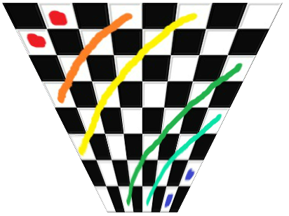
Here is an image with some important information about our trapezoid. On right right is the texture coordiantes. It’s important to know that 0,0 is the top left and not the bottom left.
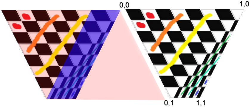
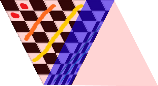
The colourful image on the left is showing what shapes the graphics card is trying to texture. The bizarre slanting of the textures makes more sense if you think about what shape the triangle thinks it’s a part of. You can see the top triangle is trying to draw a big rhombus and the bottom triangle is trying to draw a much smaller one.
If you think of it like this it becomes pretty clear that we just want to divide the x coordinate by 1-y coordinate. The top pixels are correct, and they get more wrong as they approach the bottom. Dividing them by 1-y will divide them by the range 1-0 which isn’t strictly correct unless the bottom trapezoid is zero length, but it’s much closer than what it’s doing now. Instead of the range 1-0 we really we want to divide by the range 1-.25 because the bottom is 100 pixels and top is 400 pixels. 100/400 = .25 and since it’s trying to draw a bottom that is 400 pixels wide multiplying by .25 will result in a 100 pixel bottom. (remember, since we’re working in UV coords bigger numbers result in the texture being squeezed more so if you want to decrease the size you divide by .25 instead of multiply).
Now we could do that with this pixel shader:
mov ft2 v1 //v1 contains our UV coords
mov ft3 v1 //ft3 will contain our modified y coord
mul ft3 ft3 fc4 //multiply by 1-ratio of bottom to top. In this case fc4 contains .75
sub ft3 fc1 ft3 //y = 1-y Now ft3.y contains values from 1 to .25 (fc1 contains 1)
rcp ft3 ft3 //y = 1/y there is no divide operator so we multiply by the reciprocal
mul ft2.x ft2.x ft3.y //do the real work
tex ft1, ft2, fs0 <2d,linear,repeat,mipnearest> //sample the texture
mov oc, ft1 //output
 Which results in the image on the right. Pretty cool eh? The top triangle is now correct! Unfortunately the bottom one is fucked. Plus we got here by passing the bottom/top ratio through a shader constant which isn’t going to work with variable shaped trapezoids unless we draw them one triangle at a time. Which is not going to fly.
So we need to generalise this to the bottom triangle as well as figure out a way to pass the shader the needed information. Obviously it’s time to fire up the VertexBuffers!
First lets take a quick peek at how we’re passing in the points and the UV coordinates. Here is some code:
triangles.push(new point(0, 0), new point(150, 300), new point(400, 0));
triangles.push(new point(150, 300), new point(400, 0), new point(250, 300));
for (var i:int = 0; i < triangles.length; i += 6) {
  mVertexData.setTexCoords(i, 0, 0);
  mVertexData.setTexCoords(i+1, 0, 1);
  mVertexData.setTexCoords(i+2, 1, 0);
  mVertexData.setTexCoords(i+3, 0, 1);
  mVertexData.setTexCoords(i+4, 1, 0);
  mVertexData.setTexCoords(i+5, 1, 1);
}
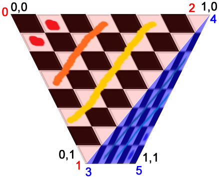
On the right I’ve numbered our points as well as reminded us all what the UV coords for those points are. The biggest thing we need to do now is to start passing the Bottom/Top ratio to the shader. We’re going to do that by passing them into the shader through a vertex buffer. I’m using Starling so I modified the starling VertexData class to hold my data but however you usually pass in your vertex buffer is cool. The important thing is that somewhere you have a line that looks kind of like this:
context.setVertexBufferAt(1, mVertexBuffer, VertexData.PERSPECTIVE_OFFSET, Context3DVertexBufferFormat.FLOAT_3);
Note that I named the collection of variables I’m about to pass in Perspective variables. Because it’s kind of a perspective transform we’re doing.
We could, at this point, just pass in Bottom/Top which would look something like this (remember, your mVertexData has no .setPerpectiveCoords, I added that):
var w1:Number = mTriangles[i + 2].x - mTriangles[i].x
var w2:Number = mTriangles[i + 5].x - mTriangles[i+3].x
mVertexData.setPerpectiveCoords(i, w2/w1);
But we can actually do better than that. We can do some of the math for the shader, which will be way faster than doing it for every pixel. Lets see what that looks like:
//Set the UV coords
mVertexData.setTexCoords(i, 0, 0);
mVertexData.setTexCoords(i+1, 0, 1);
mVertexData.setTexCoords(i+2, 1, 0);

//prep our perspective vals. We want this to go from 1->.25
var val0:Number = 0;
var val1:Number = 1;
val0 *= (w2/w1)-1; //0
val1 *= (w2/w1)-1; //-.75

val0 = val0 + 1; //1
val1 = val1 + 1; //.25
mVertexData.setPerpectiveCoords(i, 1, val0, 0);
mVertexData.setPerpectiveCoords(i+1, 1, val1, 0);
mVertexData.setPerpectiveCoords(i+2, 1, val0, 0);
This is actually pretty clever. Remember that anything passed from the vertex shader to the pixel shader is linearly interpolated. We use that by passing in 1 to the top points and .25 to the bottom point and let the video card do the work for us. Unfortunately we can’t also do the divide because the graph of 1/x is not a linear graph and so the transformation gets effed. That means our shaders now look like this:
Vertex:
m44 vt0, va0, vc0
mov v0, va1 //pass in our perpective data
mov v1, va2 //pass in the UV Coords
mov op, vt0
Pixel:
rcp ft3 v0 //y = 1/y
mul ft2.xyzw v1.xyzw ft3.yxzw //multiply TexCoords.x by 1/y
add ft2.x ft2.x v0.z //translate by some amount (we haven't discussed this yet)
tex ft1, ft2, fs0 <2d,linear,repeat,mipnearest> //grab the pixel
mov oc, ft1 //out
Magic! Our top triangle is now tops! Time to move on to the bottom one. The only tricky think about the bottom one is that its x and y coords are the reverse of what we want. The top one was easy because 0,0 was always correct but for the bottom triangle 1,1 is always correct and 0,0 is the most wrong. The solution? Pass in the UV coords upsidedown! Do the math on the upsidedown coords and then flip them back.
Here is what that looks like:
//Old UV coords
//mVertexData.setTexCoords(i+3, 0, 1);
//mVertexData.setTexCoords(i+4, 1, 0);
//mVertexData.setTexCoords(i+5, 1, 1);*/
//fliped Coords
mVertexData.setTexCoords(i+3, 1, 0);
mVertexData.setTexCoords(i+4, 0, 1);
mVertexData.setTexCoords(i + 5, 0, 0);
val0 = 0;
val1 = 1;
val0 *= (w1/w2)-1; // w1/w2 instead of w2/w1
val1 *= (w1/w2)-1;
val0 = val0 + 1;
val1 = val1 + 1;
val0 = -val0; //Flip the sign so that when the x is multiplied by 1/y it will flip the sign of x
val1 = -val1;
mVertexData.setPerpectiveCoords(i+3, -1, val0, 1);
mVertexData.setPerpectiveCoords(i+4, -1, val1, 1);
mVertexData.setPerpectiveCoords(i+5, -1, val0, 1);
Note -1 in the perpective coords. If you go back and look at the pixel shader you will see we multiply the y value by perspectiveCoords.x. By passing in -1 we flip the y axis. We flip the x axis by passing in a negative perspectiveCoords.y value.
ALMOST DONE!
The bottom triangle is fixed and this works for arbitrarily shaped trapezoids. The only problem is that it only works for texture coords from 0 to 1. But in real life our texture coords are usually things like 4.5 to 4.8 or 2.2 to 5.8 (in my application the y is always 0 to 1 though). That’s what this shader line is about:
add ft2.x ft2.x v0.z //translate by some amount (we haven't discussed this yet)
We just do all our math from 0 and then add back however much we want. If you look at these lines:
mVertexData.setPerpectiveCoords(i+5, -1, val0, 1);
And replace the , 1); with , 4.5); or , 2.2); or whatever texture coord you want you will get your desired translation. To set your desired width you just pass the width in to the UV coords as usual:
mVertexData.setTexCoords(i, 0, 0);
mVertexData.setTexCoords(i+1, 0, 1);
mVertexData.setTexCoords(i+2, desiredLength, 0);
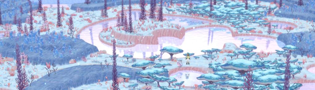
Now we really are truly finished and we are rewarded by beautiful globby circular level layouts like this:
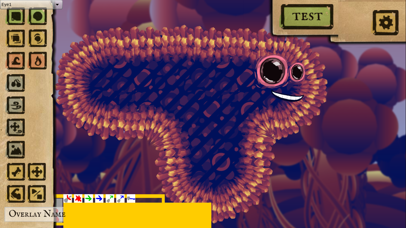
Callooh! Callay!


